Before using the virtual touch screen mode (VT mode) of aeroTAP evo, you need to perform calibration.
When you perform calibration, a virtual touch screen surface will be created in the 3D space within 60cm from aeroTAP 3D camera (120cm for aeroTAP 3D GS camera). Then position adjustment will be performed between it and the actual monitor screen.
A special tool will be used to perform calibration; aero3DCalib.exe. This tool is not released to the public. Please contact us if you are interested.
System Requirements
The following system requirements are required to run aero3DCalib.exe.
Windows 10 OS, 64bit version
CPU: Intel Core i5 or above
USB 2.0/.3.0 port (aeroTAP 3D GS camera needs USB 3.0)
Additional information: These system requirements differ from that of aeroTAP evo.
How to connect
Run the calibration tool on the system you plan to use VT mode. If you cannot run the calibration tool on the target system, use a PC that meets the requirement and connect the monitor with the target system as a external monitor. This will enable you to perform calibration.
To use as an external monitor, use the command line parameters.
Steps for configuration
The following are the rough steps for calibration.
1. Setting up the environment
Connecting the monitor of the target system, camera setup
2. Run calibration tool
a. Set the camera view and cropping
b. Sett Offset Z (distance from the center of the camera - center of the rotation axis) and rotation angle of the camera
c. 3D Box filter configuration after rotation (if needed)
d. Set the Virtual Touch Screen surface
e. Set the hover surface
f. Set the virtual screen position (adjust the buttons ① to ④)
g. calibration (4point alignment)
h. Save settings with s-key and exit with Esc-key TouchPanel.txt file will be saved in the data folder.
3. Launch aeroTAP evo
a. Load calibration parameter Read the saved TouchPanel.txt. b. aeroTAP evo configuration
Video
Configuration menu
You can display the configuration menu by pressing g-key when running aero3DCalib.exe. Other than using the configuration menu, you can also configure main features using the keyboard.
Name of menu
Description
QVGA-VGA-HD
Select the resolution that fits the camera in use.
CAM resolution
Please select the type of camera you are using.
aeroTAP 3D Camera - VGA, WVGA(640x400) recommended aeroTAP 3D GS Camera - HD(1280x720) recommended aeroTAP 3D G2 Camera - HD(1280x720) recommended
Show Cam1 Depth Filter
Please check that all are marked. If the camera is not connected, "Cam1" will not be marked. Check the connection and make sure it is marked ON.
*When using aeroTAP3D G2, to set Depth Filter OFF is recommended
Pixel Size
Pixel size when 3D point cloud is displayed (value 2-4 is recommended)
Max Depth
Set the Depth filter for the camera. Adjust according to the monitor size and/or the position of the camera. Example: 15 inch monitor 400mm 55 inch monitor 1200mm
Show Max Plate
The surface defined with the distance filter (Max Depth) will be displayed in BLUE.
Scale
A value to simplify the point cloud, Value = 4 will be used.
Adjust by Head Angle
Head Angle X,Y,Z
Enable tilt of camera. Enable the 3D display of rotation for each axis of the camera. You can switch with a-key.
OffsetZ
The center point for 3D rotation, distance from the camera Please align according to the monitor size and camera position. Usually, the distance from the camera to the hand/finger should be set to that of when placing the hand/finger in the center of the monitor
Additional information: According to the hover position, you may need to set it to where you place your hand/finger slightly below the center of the screen.
Top Filter Range, Num
Parameter to remove the noise for the top point using Outlier. Voxel size (mm) - about 10mm Minimum number - You can remove noise with bigger values but if it is too big, thin lines such as fingers can not be seen.
VertexCntMin,VertexCntMax
Min Minimum for point cloud to detect the top point, high values may cause more noise. At low values touch detection will be more sensitive and for high values the detection will be more accurate.
When using Multitouch mode, the point cloud of each fingertip will be evaluated.
Max Threshold value for finger detection, for exceeding values, the finger will not be detected
The current value will be displayed on the upper left of the screen. (Top Points)
Show Touch Plate
Touch Plate Distance Hover from TouchPanel Size of Top Sphere
Displays the position of the virtual touch screen (yellow surface) Position of the touch screen (mm). When the configuration menu is not displayed, you can adjust the position with the right/left arrow keys of the keyboard. Position of the hover surface (distance from the touch screen surface in millimeters) The display size of the fingertip (when it reaches the touch screen surface, it will turn RED)
Show Line To Target
Displays a white line from the camera to the OffsetZ position. Turn this ON to visualize the OffsetZ position.
Show Distance
Displays the coordinate in 3D space for the fingertip position
Enable Crop
Crop Left Crop Top Crop Width Crop Height
Crop Table Form
You can check the camera view area with the color display on the upper right. Unnecessary parts of the camera view will be cropped. Adjust the setting so that unnecessary things will not be displayed with you. Define the rectangle with the pixel of the camera image.
To crop with a trapezoid shape, adjust the value around 100.
Enable 3D Crop
3D Box (width, height, length) 3D Box position (X, Y, Z after rotation)
When you turn this ON, the point cloud will be filtered after 3D rotation and removes unwanted parts such as the floor. Filters the rotated point cloud by defining the size and position of the 3D Box.
Show In 3D
Displays the current point position. Detects if the position on the touch screen surface is touched or not. BLUE indicates hovering status GREEN indicates touching status Notes: Without calibration, points will not be displayed on the correct point.
Number Btn Size
The size of the buttons ① to ④, which are used for calibration.
Detect Most Top
When set to ON, the top point after rotation will be detected as the top. Normally set to ON.
Enable BGS
Keep this setting OFF.
What to do
You can switch to the help about key operation using the h-key. Information about basic key operations will be displayed.
What you want to do
What to do
Show/hide the advanced menus
Press g-key to show/hide the menu.
Switch pages of the Menu
[/] key or Page Up/Down key
Reset the settings
Press the 0-key to reset the settings.
Rotate the 3D image
Drag at the center of the screen to rotate the 3D model. Use the mouse wheel to zoom in/out.
Reset the rotation of 3D image
Press the Home key to initialize the rotation of the 3D image.
Show/hide Help
Press the h-key to show/hide the Help screen.
Rotate X-axis of the virtual camera
Press +/- key to adjust the X-axis rotation of the virtual camera.
Change the position of the Virtual Touch Screen surface
Press the right/left arrow key to move the touch screen surface to the front/back.
Save settings
Press s-key to create paramTouch.txt with the current setting parameters.
Show/hide the camera view
Press v-key to show/hide the camera view on the top right.
Switch 3D/2D view
z-key
Color display the point cloud/distance
x-key
Switch to Demo mode
Switch by Space-key You can perform a demo using the calibration result.
Switch pages of the Advanced Settings
Switch pages with [ / ] keys
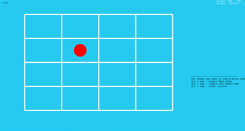
Demo mode
When you press Space key, the setting mode will switch to demo mode.
With demo mode, you can check the calibration setting. To set the size and the position of the border, press g-key in Settings.
You can switch the demo using m-key.
Boot parameter
If you want to run aero3DCalib.exe on an external monitor, use the following parameter.
aero3DCalib.exe -x1920
-x1920 indicates the x coordinate of the startup monitor. With the resolution of 1980x1080 for the main monitor and an external monitor to the right of it, using this parameter will enable the display on the external monitor.