このチュートリアルでは、Unity エディターで 3D ポイントクラウド (点群) を作成する方法を紹介します。そのためには、センサー (RGB カメラ付きが理想的) と Nuitrack SDK、オプションでモバイル端末が必要です。ポイントクラウド (点群) は、3D モデリング、3D ゲーム、VR アプリ等色んな場面で使用できます。ポイントクラウド (点群) は、センサーから取得した色と深度データを基に作成されます。
このプロジェクトを作成するために必要なものは以下の通りです。
- Nuitrack Runtime と Nuitrack SDK
- サポートされている aeroTAP 3D センサー
- Unity 2019.2.11f 以上
完成済みプロジェクトは Nuitrack SDK: Unity 3D > NuitrackSDK.unitypackage > Tutorials > Point Cloud にあります。
左がaeroTAP 3D USB Camera、右がaeroTAP 3D USB Camera GS
環境のセットアップ
- Unity でシーンを新規作成するには、[File] > [New Scene]コマンドを使用します。
- シーン内に四角を2つ作成するために、[GameObject] > [3D Object] > [Quad] (x2) を使用します。これらを、センサーから得た色と深度を表示するための平面として使用します。利便性を考慮して、深度用には、 QuadDepth、色用には QuadColor と名前を付けます。
- その後、深度と色用にそれぞれ素材を作成します。[Project]タブで[Assets]フォルダーの中に[Materials]フォルダーを作成します (右クリック > [Create] > [Material])。利便性を考え、素材に ColorMaterial と DepthMaterial と名前を付けます。
-
Nuitrack SDK をダウンロードします。Nuitrack と Plugins フォルダーを NuitrackSDK.unitypackage からプロジェクトにインポートします。NuitrackScripts プレハブを [Nuitrack/Prefabs]フォルダーからシーンにドラッグ アンド ドロップします。Unity の[Inspector]タブで[Nuitrack Manager]を選択し、[Color Module On]と[Depth Module On]のチェックボックスをオンにします。ご覧のとおり、これらの Nuitrack モジュールは、センサー深度と色へのアクセスを可能にします。他の Nuitrack モジュールは、このプロジェクトには必要ありません。
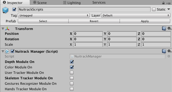
必要なモジュールを Nuitrack Manager で選択します。
- 空のオブジェクトを作成し、「Visualization」と名前を付けます。このオブジェクトを使用して、深度と色を視覚化します。
- このオブジェクトのチェックボックスをオフにします。NuitrackManager の [Init Event (NuitrackInitState)]で[+] を選択します。Visualization オブジェクトを 作成した フィールドにドラッグ アンド ドロップします。ドロップダウン リストから GameObject/SetActive を選択します。これにより、Nuitrack の初期化が行われてからに視覚化が開始されます。シーンのセットアップが完了したなら、深度と色の作業に取り掛かることができます。
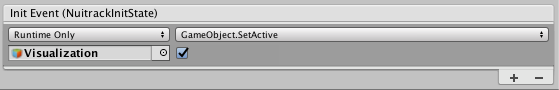
Visualization オブジェクトを選択
深度と色の視覚化
-
新しいスクリプト、PointCloud.cs を作成します。Visualization オブジェクトにドラッグ アンド ドロップします。Unity の[Inspector]タブ (Point Cloud (Script) セクション) でオブジェクトにいくつかの特性を追加します。やるべきこと:
- たった今作成した2つの素材を指定
- ポイント クラウド (点群) が表示されるウィンドウの解像度を指定
- センサーに RGB がない場合、ポイント クラウド (点群) の色付けに使用するデフォルトの色を指定
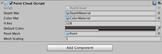
Point Cloud オブジェクトの特性
-
PointCloud :MonoBehaviour クラスで、深度と色を表示するためのフィールドを作成します。深度と色の値を保存する変数を作成します。
public class PointCloud :MonoBehaviour
{
[SerializeField] Material depthMat, colorMat;
nuitrack.DepthFrame depthFrame = null;
nuitrack.ColorFrame colorFrame = null;
}
-
解像度のフィールドを作成します (高さのみ指定し、幅は自動的に決定されます)。ピクセル サイズも定義します (frameStep)。
[SerializeField] Material depthMat, colorMat;
[SerializeField] int hRes;
int frameStep;
}
- 注意
- 推奨される画像解像度は、128х96 です。さらに高い解像度を設定することもできます。しかし、その場合、コンピューターの処理能力が低いと、Unity の動作が遅くなるかもしれません。
-
デフォルトの色を設定します (センサーに RGB がない場合、ポイント クラウド (点群) の色付けに使用)。
int frameStep;
[SerializeField] Color defaultColor;
}
-
作成した2つの平面に関するテクスチャを設定します。その後、深度を含む配列と色を含む配列を作成し、センサーから取得したデータを保存できるようにします。
[SerializeField] Color defaultColor;
Texture2D depthTexture, rgbTexture;
Color[] depthColors;
Color[] rgbColors;
}
-
初期化を定義する変数を作成します (初期化後に値が true に変更されます)。
Color[] rgbColors; // Array with colors
bool initialized = false;
}
-
視覚化を初期化します。
bool initialized = false;
void Start()
{
if (!initialized) Initialize();
}
}
-
void Initialize() メソッドで、nuitrack.OutputMode mode = NuitrackManager.DepthSensor.GetOutputMode() メソッドを使用することにより、解像度の構造、FPS、センサーの FOV を取得できます。frameStep が 0 以上であることを確認します。frameStep の値が大きいほど画質はよくなる一方、パフォーマンスは低下します。その後、メッシュ (キューブ) インスタンスを作成します。
if (!initialized) Initialize();
}
void Initialize()
{
initialized = true;
nuitrack.OutputMode mode = NuitrackManager.DepthSensor.GetOutputMode();
frameStep = mode.XRes / hRes;
if (frameStep <= 0) frameStep = 1;
hRes = mode.XRes / frameStep;
InitMeshes(
((mode.XRes / frameStep) ),
((mode.YRes / frameStep) ),
mode.HFOV);
}
}
なぜ if (frameStep <= 0) frameStep = 1 を設定しなければいけいないか疑問に感じるかもしれません。frameStep が 1 より小さい少数の場合、切り捨て 0 になります (frameStep は整数)。この場合、Unity または携帯端末がクラッシュしますが、それは、frameStep による除算がスクリプトに含まれているからであり、ゼロ除算が行われようとする結果といえます。0 よりも小さい少数の値は、センサーの解像度が Unity で設定されている解像度よりも低い場合に生じます。例えば、センサーの解像度が 80x60 で Unity での解像度が 128x96の場合等がそれに該当します。
-
void InitMeshes メソッドを使用して、テクスチャを作成し、それを素材に適用し、配列のサイズを設定します。
mode.HFOV);
}
void InitMeshes(int cols, int rows, float hfov)
{
depthColors = new Color[cols * rows];
rgbColors = new Color[cols * rows];
depthTexture = new Texture2D(cols, rows, TextureFormat.RFloat, false);
depthTexture.filterMode = FilterMode.Point;
depthTexture.wrapMode = TextureWrapMode.Clamp;
depthTexture.Apply();
rgbTexture = new Texture2D(cols, rows, TextureFormat.ARGB32, false);
rgbTexture.filterMode = FilterMode.Point;
rgbTexture.wrapMode = TextureWrapMode.Clamp;
rgbTexture.Apply();
depthMat.mainTexture = depthTexture;
colorMat.mainTexture = rgbTexture;
}
}
- 注意
- ポイント クラウド (点群) の品質向上のため、aeroTAP 3D USB センサーを利用するようお勧めします。
-
void Update() メソッドで新しいフレームを確認します。
colorMat.mainTexture = rgbTexture;
}
void Update()
{
bool haveNewFrame = false;
if ((NuitrackManager.DepthFrame != null))
{
if (depthFrame != null)
{
haveNewFrame = (depthFrame != NuitrackManager.DepthFrame);
}
depthFrame = NuitrackManager.DepthFrame;
colorFrame = NuitrackManager.ColorFrame;
if (haveNewFrame) ProcessFrame(depthFrame, colorFrame);
}
}
}
- 注意
- 新しい深度と色フレームのリクエストは、 NuitrackManager.onColorUpdate (色フレーム) と NuitrackManager.onDepthUpdate (深度フレーム) に登録することによって行えます。
-
新しいフレームを受け取ったなら、それを処理します。
if (haveNewFrame) ProcessFrame(depthFrame, colorFrame);
}
}
void ProcessFrame(nuitrack.DepthFrame depthFrame, nuitrack.ColorFrame colorFrame)
{
int pointIndex = 0;
for (int i = 0; i < depthFrame.Rows; i += frameStep)
{
for (int j = 0; j < depthFrame.Cols; j += frameStep)
{
depthColors[pointIndex].r = depthFrame[i, j] / 16384f;
Color rgbCol = defaultColor;
if (colorFrame != null)
rgbCol = new Color32(colorFrame[i, j].Red, colorFrame[i, j].Green, colorFrame[i, j].Blue, 255);
rgbColors[pointIndex] = rgbCol;
++pointIndex;
}
}
}
}
depthColors[pointIndex].r = depthFrame[i, j] / 16384f ストリングは、深度マップのレンダリングを行います。r パラメーターの値の範囲は、0 から 1、そして深度の値の範囲は 0 から 65536 となります。係数が低いほど、深度マップは明るくなります。
-
深度と色テクスチャのピクセルに色を付けます。
++pointIndex;
depthTexture.SetPixels(depthColors);
rgbTexture.SetPixels(rgbColors);
}
-
深度と色テクスチャのピクセルを視覚化オブジェクトに適用します。
rgbTexture.SetPixels(rgbColors);
depthTexture.Apply();
rgbTexture.Apply();
}
- 結果として、2つの画面が表示されます。左には色ピクセル画像、右には深度マップが表示されます。これをポイント クラウド (点群) 作成のために使用します。
Unity での色と深度平面
3D ポイントクラウド (点群) の作成
これで、ポイント クラウド (点群) 作成に必要なデータがすべて揃いました。
- [Hierarchy]タブで、Point プレハブを作成します([Create] > [3DObject] > [Cube])。キューブとして表示されます。ポイントクラウド (点群) は、これらのキューブで構成されます。
- プレハブのための素材を作成します ([Project] > [Create] > [Material] > [PointMat])。PointMat 素材を Point プレハブにドラッグ アンド ドロップします。
- ポイントクラウド (点群) は、膨大な数のキューブで構成され、それぞれが接触し、ぶつかりあうことになります。Unity がこれらすべてのオブジェクトの衝突を計算していたら、プロジェクトのパフォーマンスが大幅に低下します。これを防ぐために、Gear をクリックし、[Remove Component]を選択して、[Box Collider]要素を削除します。
- [Point]フォルダーをプロジェクト フォルダーにドラッグ アンド ドロップし、シーンから削除します。
-
それでは、スクリプトに戻りましょう。public class PointCloud :MonoBehaviour で、作成した Point プレハブのためのフィールドを作成します。
[SerializeField] Color defaultColor;
[SerializeField] GameObject pointMesh;
Texture2D depthTexture, rgbTexture;
-
Point プレハブを、このフォルダーから、Point Cloud 要素の Point Mesh フィールドへドラッグ アンド ドロップします。
-
スクリプトに、Points プレハブ (キューブ) を含む配列を作成します。
Color[] rgbColors; // Array with colors
GameObject[] points;
bool initialized = false;
-
void InitMeshes() メソッドで、配列のサイズを設定するために、Points プレハブを使用します (行数とカラム数を掛けます)。
rgbColors = new Color[cols * rows];
points = new GameObject[cols * rows];
depthTexture = new Texture2D(cols, rows, TextureFormat.RFloat, false);
-
void InitMeshes メソッドで、Points (キューブ) のインスタンスを作成し、Points 配列に追加します。Visualization を親オブジェクト、Points プレハブを子オブジェクトに設定します。
colorMat.mainTexture = rgbTexture;
int pointId = 0;
for (int i = 0; i < rgbTexture.height; i++)
{
for (int j = 0; j < rgbTexture.width; j++)
{
points[pointId++] = Instantiate(pointMesh, transform);
}
}
}
-
void ProcessFrame メソッドで、 Point (キューブ) の位置を Z (深度) 軸に沿って変更します。センサーがこのポイントの深度を認識できない場合があります。結果として、Z 座標の値が 0 になってしまいます。Z=0 のポイントを隠すことで、画像の正確な表示が可能になります。その後、Point (キューブ) の位置とサイズを変更できます。
rgbColors[pointIndex] = rgbCol;
points[pointIndex].GetComponent<Renderer>().material.color = rgbCol;
Vector3 newPos = NuitrackManager.DepthSensor.ConvertProjToRealCoords(j, i, depthFrame[i, j]).ToVector3();
if (depthFrame[i, j] == 0)
points[pointIndex].SetActive(false);
else
{
points[pointIndex].SetActive(true);
points[pointIndex].transform.position = newPos;
}
++pointIndex;
-
Unity, での距離を変更する際に、ポイントクラウド (点群) をさらにリアリティのあるものにするには、メッシュの大きさを、距離に応じてキューブのサイズが変化するよう、調整する必要があります。public class PointCloud :MonoBehaviour で、次のストリングを追加します。
[SerializeField] GameObject pointMesh;
[SerializeField] float meshScaling = 1f;
float depthToScale;
int frameStep;
-
void ProcessFrame(), で、振動に応じてキューブのサ大きさを計算するには、以下のストリングを if (depthFrame[i, j] == 0)... else... 条件に追加する必要があります。
void ProcessFrame(nuitrack.DepthFrame depthFrame, nuitrack.ColorFrame colorFrame)
...
else
...
points[pointIndex].transform.position = newPos;
float distancePoints = Vector3.Distance(newPos, NuitrackManager.DepthSensor.ConvertProjToRealCoords(j + 1, i, depthFrame[i, j]).ToVector3());
depthToScale = distancePoints * depthFrame.Cols / hRes;
}
-
void ProcessFrame() メソッドで、キューブ サイズを変更します。
depthToScale = distancePoints * depthFrame.Cols / hRes; //calculate the size of cubes as a function of depth
points[pointIndex].transform.localScale = Vector3.one * meshScaling * depthToScale;
}
-
プロジェクトのビルドを作成すると、以下のアニメーションのような、色つきのポイント クラウド (点群) が表示されます。お使いのセンサーによって、色が明るい/淡い、深度マップの詳細レベルが異なる等、結果が異なることがあります。しかし、どんな場合であれ、作成されたポイント クラウド (点群) は、プロジェクトで利用するには十分な品質です。
作成した ポイントクラウド (点群)
-
ポイントクラウド (点群) を作成しましたが、あまり立体的に見えません。ポイントクラウド (点群) の実際の容積とオブジェクトの位置を確認したい場合は、MouseOrbitImproved スクリプトを適用する必要があります。スクリプトを、Unity のカメラにドラッグ アンド ドロップします。空のオブジェクトを作成し、ここでは、”rotation point”と名前を付けます。オブジェクトを x:0 y:0 z:600 に移動します (カメラがオブジェクトの周りを回転します)。スクリプト設定で、カメラ (rotation point) が回転する際の中心となるオブジェクトを指定します。以下の画像が示すように設定します。
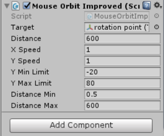
MouseOrbitImproved スクリプトの特性
- スクリプトが適用されると、オブジェクトの容積がポイントクラウド (点群) として表示されます。お疲れ様でした!
MouseOrbitImproved スクリプト適用後の 3D ポイントクラウド (点群)
便利な関連情報へのリンク:

 1.8.6 を使用
